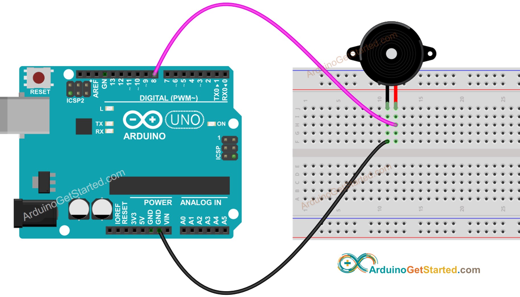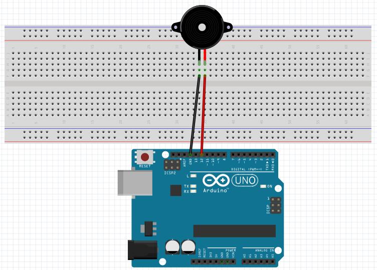

Only one tone can be generated at a time. The pin can be connected to a piezo buzzer or another speaker to play tones. A duration can be specified, otherwise, the wave continues until a call to the Generates a square wave of the specified frequency (and 50% duty cycle) on a pin.
#ACTIVE BUZZER ARDUINO CODE CODE#
We’ll be using it to set different output frequencies in the following code example in the next section. In software, we need to generate the AC signal required to drive the passive buzzer using the NoTone ( ) functions to control the passive buzzer device. Or, alternatively, we can use any digital IO pin alongside the We can use a PWM output pin to control the passive buzzer tone output. The Passive Buzzer connection to the Arduino is exactly the same as what we’ve done with the Active Buzzer. But it’s still a thing and I thought you should know about it and try it by yourself. It does indeed control the volume level of the buzzer but it also distorts the buzzer sound which is not meant to be connected to a PWM signal in the first place. Disconnect the voltage source and reconnect it again to hear the clicking sound again.

This can ease your task of identifying an Active buzzer from a passive buzzer. Passive Buzzers don’t “usually” have a backside cover, unlike the Active buzzers. Here is how you can easily differentiate between an Active buzzer and a passive buzzer: But it also allows us to generate whatever note frequency we want to play. Therefore, it’s a little bit harder to control compared to Active buzzers. Passive Buzzers on the other hand need an AC voltage signal in order to vibrate and make sound. It acts like a digital output device (like an LED or something) that you either turn ON or OFF. You only need to feed it with constant voltage and it’ll play a continuous buzzer tone until you drive it LOW. And that type is called Active Buzzer.Īctive Buzzers are the easiest to use, as they have internal oscillators. This is called a Passive Buzzer.Īnother type of buzzer doesn’t need a varying voltage, you just give it constant voltage and it has an internal chopper (oscillator) circuit that turns the constant voltage to a square wave and feeds that to the piezo disc to generate a fixed-frequency tone.

And it needs a voltage of 3.3v up to 12v to work, the working voltage is stated on the manufacturer page so make sure you get a 5v buzzer which is going to work just as fine with all microcontrollers.Īpplying voltage to the piezo buzzer terminals will cause a slight deformation in the piezo disc and by changing this voltage the piezo disc will vibrate and produce the buzzer sound we all know. Here is an interactive tool that you can play with to experience what a buzzer sounds like!Ī piezo buzzer is a polarized electronic device which means it has a positive lead & a negative lead. They are a popular choice for simple sound effects, alarms, and tone-generation applications due to their small size, low cost, and ease of use. Piezo buzzers are a type of audio transducer that can be used to generate sound. Without further ado, let’s jump right into it! Table of Contents
#ACTIVE BUZZER ARDUINO CODE HOW TO#
Then, we’ll discuss how to interface each of them with Arduino with a couple of code examples to practice what we’ll learn.

We’ll start off by explaining the differences between Active Buzzers vs Passive Buzzers. NoTone ( ) functions to create a couple of Arduino Buzzer Code Example projects. In this tutorial, we’ll learn how to use the Arduino With Active Buzzer & Passive Buzzer in your projects.


 0 kommentar(er)
